CAN on 8p8c Connectors
8p8c is not RJ45
Pedantic Warning You will often hear people call the modular connectors that are used for Ethernet "RJ45", but that standard is a very specific thing that is not actually what you're using. The correct term is an 8p8c connector, which refers to the 8 positions and 8 contacts.
I have often done this myself, but for the purposes of being technically correct, I will try my best to stick to the proper designation.
For the project, I want to connect the string of devices over CANbus. To do that, I intend to leverage the ubiquitous 8p8c that you see all over the place in Ethernet.
Goals
There were a few goals in mind:
- Use existing standards and easily available connectors and cables
- Deliver power over the same cable as the signal
- Provide reasonable noise immunity
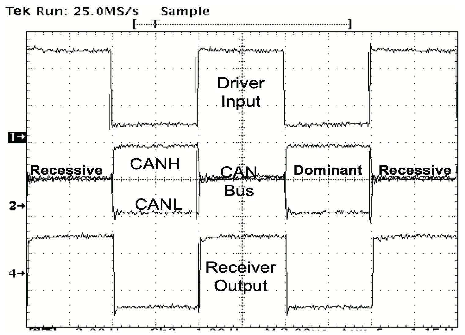
The noise immunity is pretty easy given this is a differential signal and we are going to use twisted pairs to twist the high and low signal together. Looking at an oscilloscope trace of the CAN signal from this TI application note, you can see the differential nature:
Connector Signal Mapping
For the ends, I chose to use a rather boring layout, but I wanted to make sure CAN was twisted together, and that each of the +12V wires was also twisted with a ground.
Cable Wiring
The wiring is standard Ethernet wiring, following the T568A standard. The reality is that it doesn't matter whether you use T568A or T568B, quite honestly, but I just picked A because it's the most common and what the typical patch cable is wired for.
Category 5/5e is more than adequate for the signalling that CAN or CAN FD use. The general rating for Category 5 is 100MHz, and if we look at a quality cable, like the Belden 1224, we can see that it has the following characteristics:
| Max DCR | Max DCR Imbalance | Max Capacitance | Insertion Loss(100MHz) | Fitted Impedence |
|---|---|---|---|---|
| 89Ω/km | 3% | 33pF/100m | 21dB/100m | 100±15Ω |
And it is, in fact, rated to 350MHz, far in excess of what's needed.
The makes the overall wiring looks like this:
Power Handling
Voltage Smoltage
I haven't actually settled on the voltage to use on the cabling. For now, I am using +12V, but moving up to +48V would (basically) quadruple the available power without requiring any additional copper. It does, however, somewhat complicate the individual device power supplies.
At this point, I'm planning to run +12V across the cable to allow for most things to be powered off the central device. Given I use solid rather than stranded cables, we can the standard AWG wire gauge ratings of 3.5A on a 24 AWG single-core wire.
Now we can't do the math quite yet, as we need to derate the wire based on two different factors, according to the NEC:
- Ambient operating temperature
- More than 3 wires in a cable
So, if we do the math for operating at 40C (104F), and with the 3 power carrying conductors in the cable, we get derating factors of 0.88 and 0.80 respectively. So...
So that means we can do 7.392 * 12 = 88.7W of power on the cable. But there's a catch. The current most advanced power-over-ethernet (PoE) standard, IEEE 802.3bt-2018, says that each pair of conductors is designed to handle 960mA, which would actually put us at (generously!) 960 × 2 or 1.92A, or 23W at 12V.
This is the reason I'm thinking of switching to driving the cable with 48V, which would let me move up to 92W, which is about what the standard allows. So, perhaps I will change to a 48V distribution, which will require something like an LM5576.
We'll burn that bridge when we come to it.
Quick Note About Diagrams
The diagrams above were done with an amazing tool called Wireviz, and embedded into the MkDocs site you're reading using a little hacky Markdown extension I wrote.