Willkommen. Bienvenue. Welcome. C'mon in.
I'm going to try and do something new with this project, and that's to document the messy convoluted process that my brain goes through to do anything. Historically, I've largely kept that all to myself, and not surfaced anything until the end, if even then.
Inspiration
The inspiration for this project was a post on Hackaday, which I can no longer find, which pointed to this project, which was a wildly over-engineered home automation project based around 19" subrack and a custom protocol built on top of RS-485. You can find the full project on GitHub, and there's even an amazing deep dive YouTube video
The absurd over-engineering really appealed to me as a project to tackle, and a way to push my embedded hardware and software skills way further than I have historically. I cannot emphasize enough just how much I've been inspired by their work. Some things I've lifted nearly wholesale are:
- Leveraging a subrack. This gives a physical structure to the system, but also lets me build a backplane-based system as well.
- Eurocard sized modules, and use of the DIN 41612-style connectors.
- Doubling up the connector pins to simplify the backplane routing. This
means that both the
aandbrows are the same signal, allowing for a straight line bus. - Leveraging 8P8C for connectors on the network.
- Designing a main Eurocard base for a vast majority of the work. The idea of having a single PCB that can be adapted to a bunch of different uses is very appealing
- Putting power for the backplane into a slot.
- Leaning into a specific "vibe" for everything that has a bit of an alternate timeline feel to it.
There's also this project that applies SCADA to the situation, but this just didn't "vibe" with me as an approach.
Goals
When it comes down to it, I have absolutely no need for this project. It doesn't solve a gap in my life, as I have HomeKit for a lot of things. Instead, I have a few goals with the project:
- Learn. This is the #1 goal by a wide margin. So what do I want to learn?
- Designing with modern surface-mount technology, and that includes
working with fine-pitch packages, tiny (0402) passives, and various
leadless
packages.
- Build some understanding of modern power supply systems, such as switch mode power supplies.
- Dig into modern embedded frameworks.
- Push my ability to do the full integration from top to bottom of a project.
- How to design seriously resource constrained protocols.
- Build something silly and a bit absurd. Nobody needs this, so lets have some fun.
In addition, there's some stretch goals/features I hope to (eventually) explore:
- A mechanism to do updates across all the nodes with a single experience. Thinking about how I might use CAN to update the firmware on everything, perhaps when a USB drive with the proper data in the proper structure is inserted. This will be non-trivial, but also I'm going to skip the insane security complexity because this is not a thing on the Internet. If that ever changes, then that consideration will have to change. mcuboot offers some capabilities here that I hope to leverage.
- Integrating WiFi for a needlessly complicated time source. This will likely be done using an ESP32 series module as an co-processor.
- Integrate self-monitoring/analysis into the designs. This would allow the MCU to also check everything about itself. Perhaps using an analog switch like the 74HC4067 connected to the ADC within the MCU, and a digital power monitor, like the INA series from TI. This is inspired by how a lot of test equipment can verify its own function.
Decisions So Far
Part of the process of getting started for me is doing a ton of research and then making some critical decisions that shape the project's overall strategy.
Eurocard/Subrack/Backplane Structure
A Rant About Standards
One of the most exhausting parts of doing this project has been trying to find the international standards that I've mentioned. I've been fortunate through some search-fu to find copies of the PDFs that are typically very expensive. Go support Carl Malamud and the fundamental work he's doing to make law and standards more accessible.
I really like this decision in the inspiration project. I had been thinking about building a modular sensor system in this format, and this gave me a better idea to work with in this case. I'm intending to use a 3U (133mm, 5.3") subrack, and am exploring a couple of different widths. The standard width (19", but also called 84HP) is the easiest to get, but it's a bit large for what I'm trying to do. I'm also planning to use a 175mm (6.89") standardized depth because this isn't that deep for home use, and doesn't necessarily require it to be put into a physical rack (which I don't have space for).
Fortunately, subrack products aren't particularly expensive, and I've been 3d printing mock-ups to explore the physical form factor better.
For the cards themselves, I'm intending to use the base Eurocard specification, which is 100x160mm. I'm trying to figure out if it's possible to move to the 100mm depth, which would both result in a smaller footprint, but also fit within the "cheap" sizes for most of the Chinese PCB manufacturers, which would reduce the cost overall.
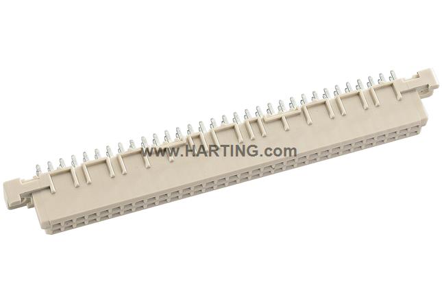
For the backplane, I'm using VMEbus for mechanical inspiration, but have designed my own signaling assignments because I'm not building a general purpose bus, but one designed for very specific purposes that benefits from decades of changes in the microcontroller ecosystem. The connectors will be type B DIN 41612 with 64 contacts in 2 rows. The Harting part is shown to the right. The connectors also have a 2A per contact current carrying capacity, which means they can be used to cary a decent amount of power.
STM32 Microcontrollers
kha is built on the AVR microcontroller ecosystem. This is a very well regarded 8-bit MCU platform that has been around for quite some time. It's widely used in hobbyist and embedded projects. That would be a great choice, but I decided to go with the ubiquitous STM32 series of ARM-based microcontrollers. You might know them from the Blue Pill and Black Pill boards. ST has a bewilderingly broad product set to work from, and have a competitive price point for something with wildly more capability.
I've settled on exploring 3 different chips:
| Chip | Core | Flash | RAM | CAN | Price (25 unit) |
|---|---|---|---|---|---|
| STM32G0B1RE | M0+ @ 64Mhz | 256Kb | 144Kb | 2 x CAN-FD | $5.5140 |
| STM32F072RB | M0 @ 48MHz | 128Kb | 16Kb | 1 x CAN | $4.8544 |
| STM32H503RB | M33 @ 250MHz | 128Kb | 32Kb | 1 x CAN-FD | $3.3728 |
As you can see they're all over the place. The H5 series is by far the fastest one, and the cheapest, which is curious. I've picked up Nucleo dev boards to start exploring.
While I'm going to be designing my own boards, I intend to leverage the Nucleo board schematics as a starting point for best-practices. This is a good thing.
CAN Bus
The first area where I've deviated from my inspiration is I intend to use CAN (and potentially CAN-FD). I've been working with CAN some in the robotics space, and it has a lot of nice capabilities. The inspiration used RS-485 (which is another great choice), but this also required them to implement a lot of low-level protocol capabilities that come for free with CAN.
One of the open questions is whether to use another abstraction on top of CAN. If I use "regular" CAN, there's only 8 bytes available in each packet. That may be plenty. CAN-FD allows 64 bytes. But there are other options that can extend that to nearly limitless. Some options are:
These come with higher-level abstractions, but I think they might just be too much for this specific case. I think, given the use case, 8 bytes is probably plenty.
Zephyr
I struggled with the framework to build all the software in. I've done a bunch of things, quite successfully, with Arduino, but I felt like I needed to stretch my skills, and work in something a bit more robust. I initially thought about using FreeRTOS along with ST's STM32Cube software, but I'll be honest... Eclipse gives me hives.
So, after looking at ThreadX, and a few others, I decided to build on top of Zephyr for a couple reasons:
- Huge board and chip support, and it's well supported by the vendors as well, and not just hobbyists.
- Gigantic (although nowhere near Arduino scale) ecosystem of modules and code.
- Excellent high-level primitives to build on top of, such as robust threading and IPC support, network stacks, sensor framework, and numerous other modern components.
- Even comes with things like a built in robust shell capability.
I have had a bit of a challenge wrapping my head around the workspace concept they use, but I've, I think, gotten past that now. I still don't have development working on my Windows machine, and I'd like to be able to use any platform to develop.
Where I Am Today
I am very early. I have:
- Acquired a few test boards and CAN transceivers to work with before I commit to any specific PCB design.
- Designed a breakout board for the Nucleo format to get IO onto JST PH connectors.
- Designed an initial 7-slot backplane to work with. This is subject to change in the future, and I'll need a bigger one for the full size project, but this is a good start.
- Designed a bunch of reusable schematic components that will show up all over the place.
- Built a few toy applications in Zephyr to try and better understand both the APIs, but also the odd build infrastructure that they use. I still haven't gotten it working with my Windows 11 desktop, but it works fine on my MacBook.
- Designed an initial switch mode power supply around the TPS566238 controller chip. Simulations say this should hit 95% efficiency, if not a bit above that. But, it's a dumb package, a 3x2mm VQFN. I have a backup design I've worked out built around the TPS566242, which comes in a marginally "better" SOT-53 package, with efficiency targeted around 92%. Fortunately, the passives are all the same between the two, just arranged slightly differently. This will be used to regulate the 12V backplane voltage to 5V for distribution along side. The individual boards will regulate down to their 3.3V as needed, leveraging an AP2113K-3.3 low dropout (LDO) linear regulator.
- Figured out a bunch of initial connector pin outs.
- Figured out an initial minimal protocol for communications.
Right now, these aren't in the repository, but over the next few days, I'll be moving them into here.
So, there's the big messy start to this adventure.